
Inspiration and Prototype Research
Upgrading My FEC Switcher Lights: Incandescent to LEDs
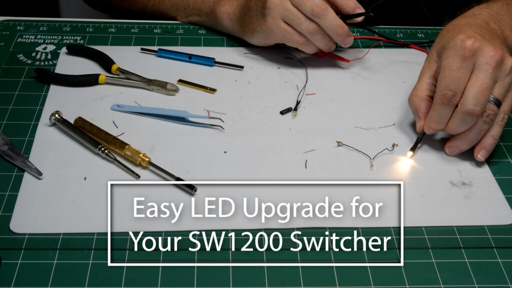
Table of Contents
Watch Along: Simple LED Upgrade for Your Florida East Coast Switcher
How I Replaced Incandescent Lights with LEDs on My Model Switcher
Today I’m sharing how I replaced the original incandescent lights in my Florida East Coast switcher with LEDs. This is part of prepping for a larger DCC upgrade that’s coming soon, but since the DCC controller is still on backorder, I decided to tackle the lighting first. If you’ve thought about upgrading your switcher lights to LEDs, here’s a straightforward walkthrough of how I did it.
Why Replace Incandescent Lights with LEDs?
Incandescent bulbs can be inefficient and tend to burn out. LEDs are more reliable, use less power, and last longer. For the DCC system I’m planning, the track voltage will be around 14V. To protect the LED from burning out, I’m using a 1k ohm resistor in series with it. Without the resistor, the LED will pop almost instantly.
Understanding LED Polarity and Wiring
LEDs have a positive (anode) and negative (cathode) lead, and wiring them backward means no light. The longer lead is the positive side, and the shorter lead is the negative. Some LEDs show this visibly inside the casing—the bigger internal part usually corresponds to the negative side. It’s critical to wire the LED correctly.
The resistor can go on either side of the LED as long as it’s in series. For wiring, I used thin 30 AWG wire and a wire wrap tool to wrap the wire neatly around the LED leads and resistor before soldering.
Step-by-Step Wiring Process
- First, I wrap the negative wire to the LED lead with the wire wrap tool, trim the excess lead length, then solder the connection.
- Next, I add the 1K ohm resistor in series by bending one end at an angle, wrapping the wire, and soldering it.
- I cover each solder joint with heat shrink tubing to prevent shorts.
- For the positive lead, I repeat the same process—strip wire, wrap, solder, and cover with heat shrink.
- I used color coding to keep track: dark colors like brown for negative and brighter colors like red or blue for positive wires.
- Once both LED assemblies are done, I test them on a power supply at about 14V to confirm they light up properly.
Installing the Lights and Next Steps
The rear LED will go in the cab area and light up when running in reverse. The front LED gets similar treatment but with some spacing adjustments so it lays low inside the housing.
Once tested and confirmed working, the next step will be repairing the cab glass supports that broke off. Then I’ll mount the LEDs inside the locomotive and finish wiring everything up. That will be the focus of the next video.
Final Thoughts
Upgrading from incandescent bulbs to LEDs is a straightforward way to improve reliability and prepare your model for DCC upgrades. Keeping track of polarity, using the right resistor, and protecting your solder joints with heat shrink will help ensure your lights work right the first time.
If you’ve done similar LED upgrades or have questions about wiring, I’d love to hear about it. Drop a comment or share your tips—let’s help each other make our model railroads better.