
Inspiration and Prototype Research
Restoring & Upgrading a Proto 2000 SW900 – The KNR 90 Rebuild : DCC Decoder Install
Table of Contents
Learn how I fit a full-size DH187D decoder into a Proto 2000 SW900 switcher. Step-by-step process, resistor tricks, custom parts, and tips for working with LEDs in tight spaces.
Restoring & Upgrading a Proto 2000 SW900 – The KNR 90 Rebuild : DCC Decoder Install
If you’ve ever cracked open one of the Proto 2000 SW900s, you know there’s not a lot of room to work with. This is one of those “tight squeeze, but worth it” kind of projects.
Before doing any dcc decoder work, after I replaced with side frames, I started by lubricating the gears with LaBelle 102 Gear Oil and some 106 Grease. Then I added a small drop of DeoxIT D100L on the electrical pickups. It’s a simple step that makes a big difference in performance and reliability down the road.
DCC Decoder Choice
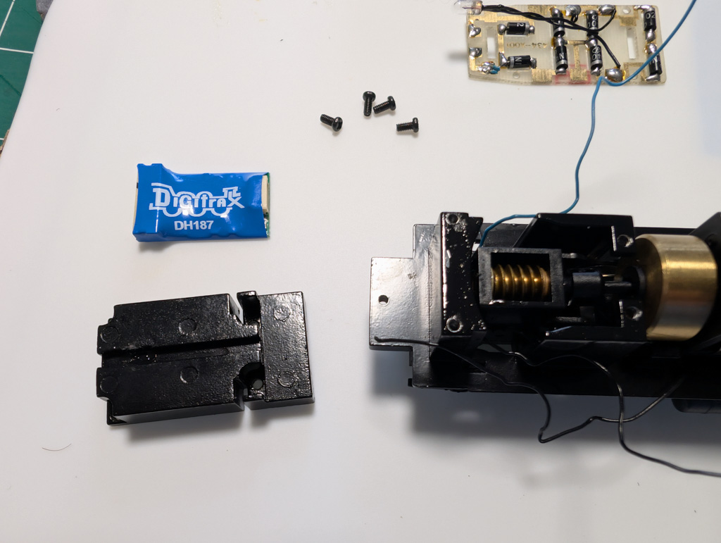
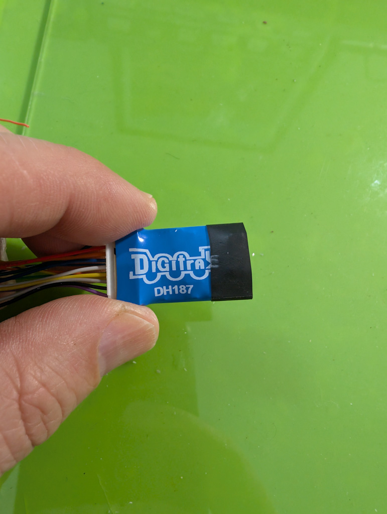
I went with a Digitrax DH187D. Why? Simple—it’s got 8 function outputs. That gives me plenty of room to do what I want:
- Front and rear headlights (2 functions)
- Front and rear ditch lights (4 functions)
- A warning beacon (1 function)
That’s 7 right there. And this thing can handle it.
The Problem
The usual advice is to use a smaller N scale decoder in these, and they’re not wrong—space is tight. But I didn’t want to give up features, so I made it work by removing the front weight. Keep in mind: doing that will limit how many cars the loco can pull. But it’s a switcher, not a mainline hauler, so that’s a trade-off I can live with.
One day I might design a small logic board so the ditch lights change automatically depending on direction—front ones on with the front headlight, rear ones with the rear headlight. But for now, I’m keeping it simple.
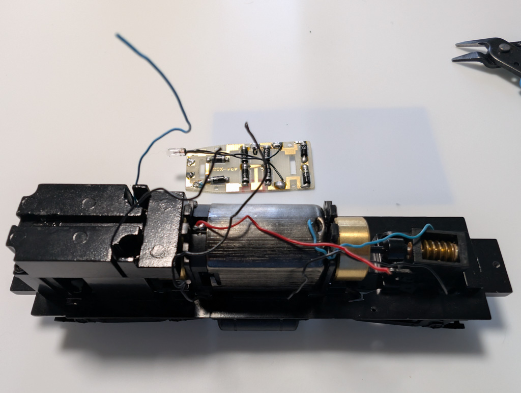
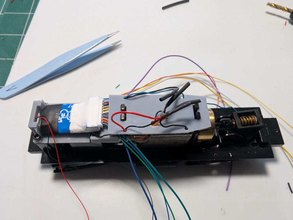
What I Came Up With
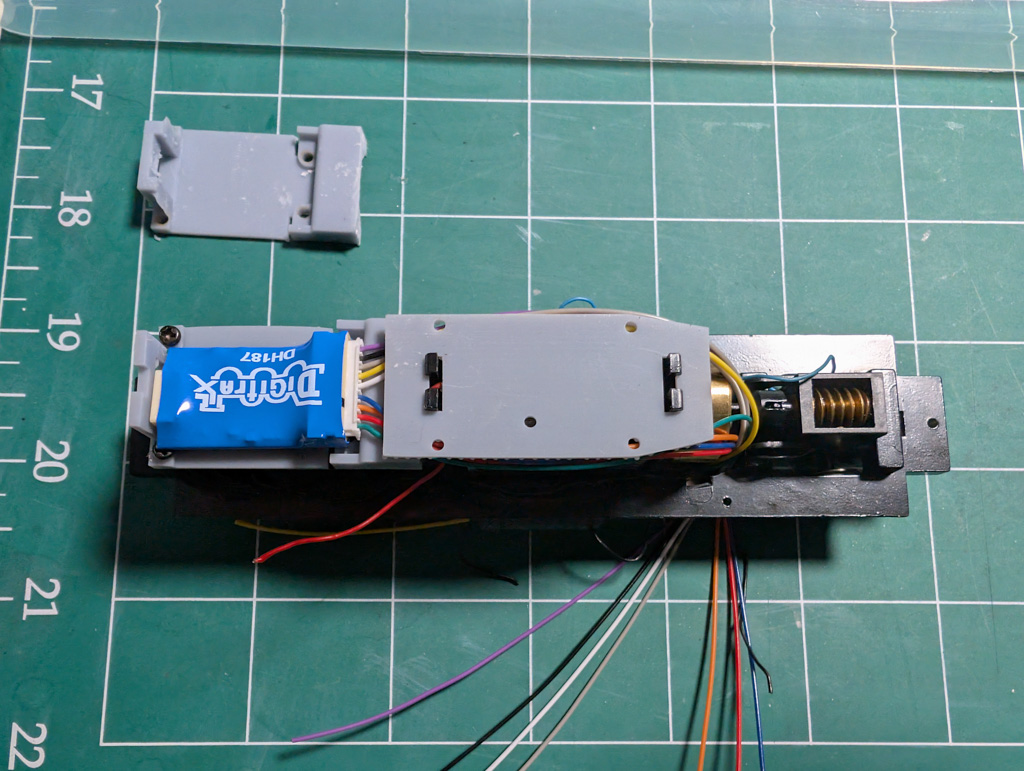
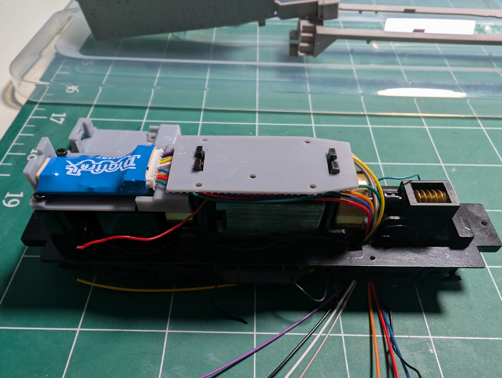
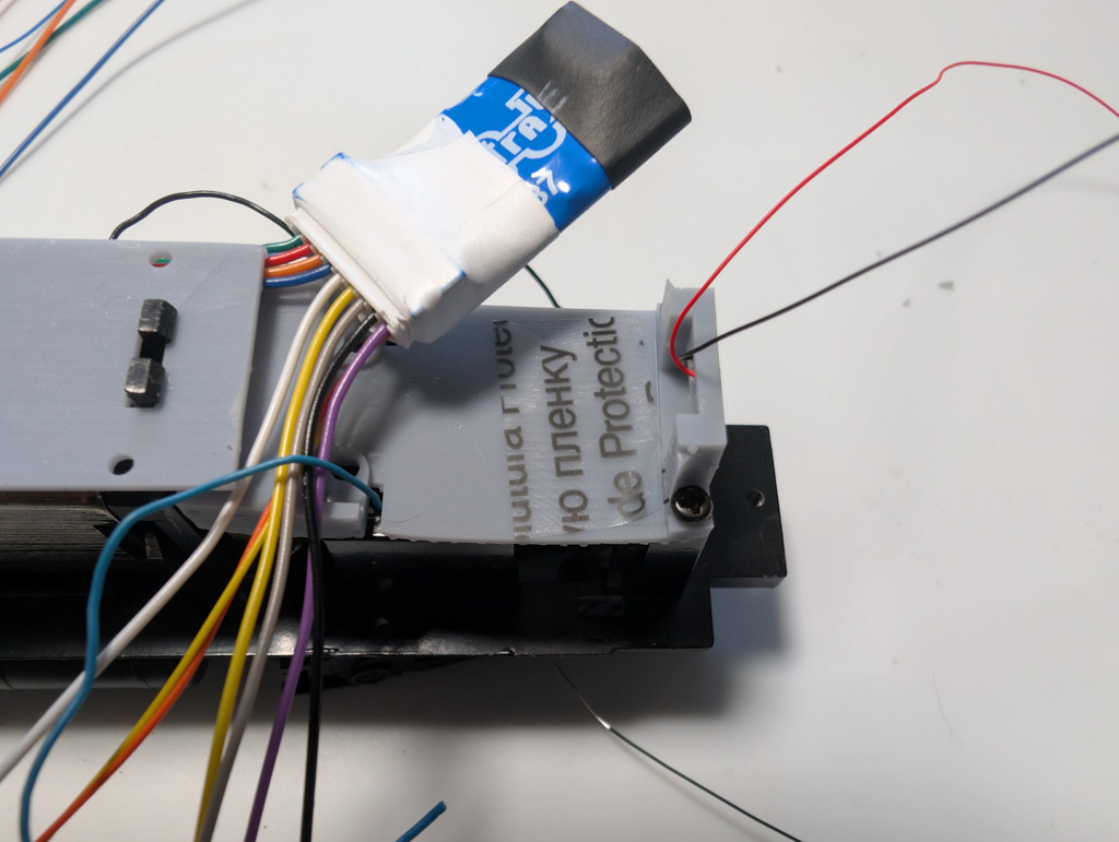
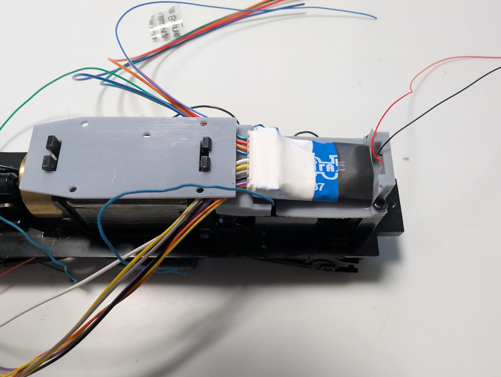
After gutting the original board and weight, I designed and printed a couple of custom parts. One goes where the original board was—it’s just a simple plate with pass-through holes to make wiring easy. The other replaces the front weight and holds the DH187D firmly in place, plus includes a mount for the front headlight LED.
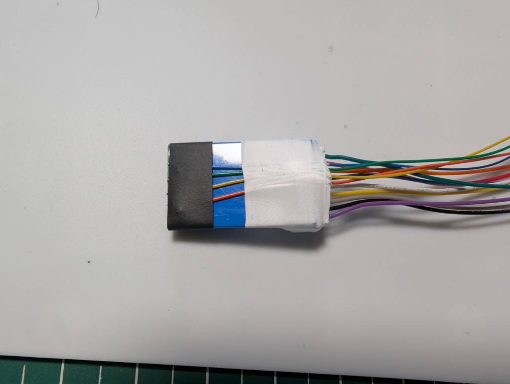
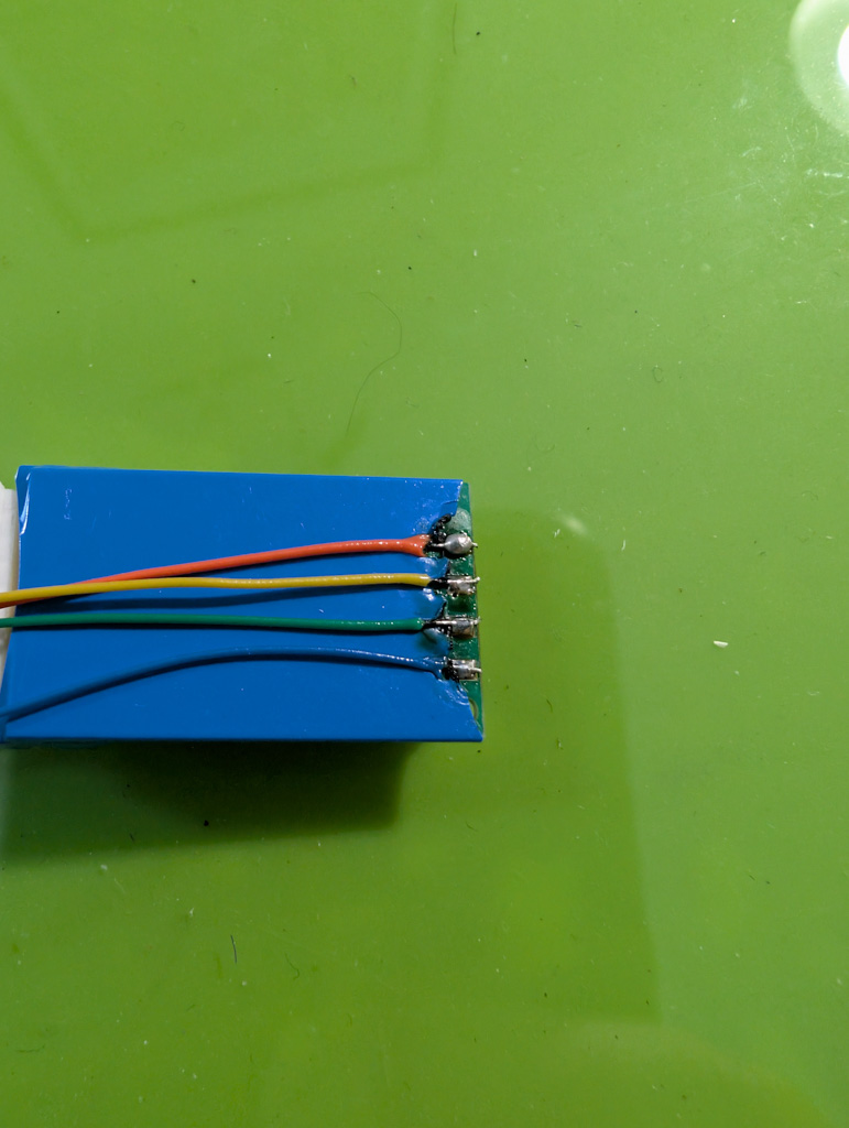
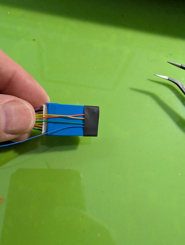
There’s not enough space to use the front 6-pin connector on the decoder, but there are function pads on the bottom side. I clipped the connector and soldered the wires directly to those pads. Heat shrink and Teflon tape kept things tidy and protected from shorts.
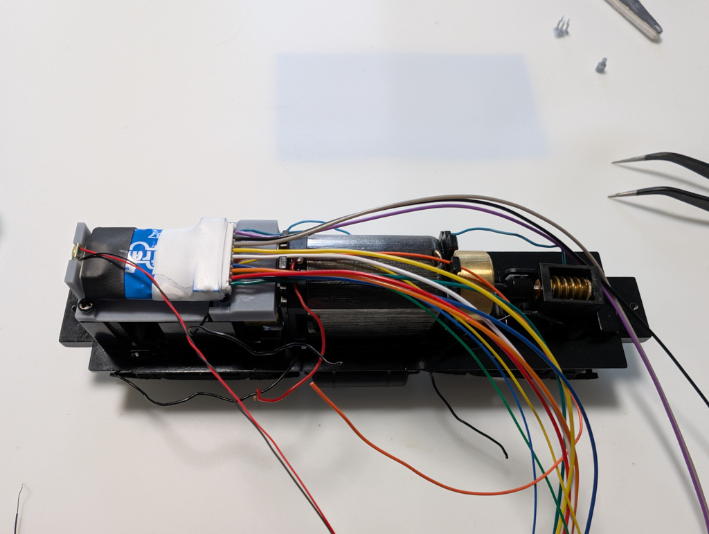
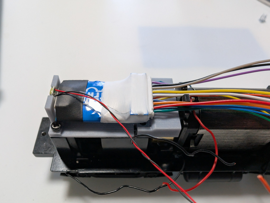
Putting It Together
For the front light, I used a warm white 1206 SMD LED. (Side note: remind me to do a post on LED color temperatures—because it does matter, especially when you’re building a layout with a specific vibe in mind.) I’ve been using UV bonding glue lately to hold LEDs in place, and honestly—I’m hooked. It stays soft until you hit it with the UV lamp. Then, boom. Solid, clear, and permanent. Great stuff.
After placing the LED, I mounted the decoder using double-sided tape and soldered the power and motor leads. Everything got capped with heat shrink for protection.
Resist The Typical Way of Doing Things
All lights on this loco are LEDs. I’m fully in the LED camp—brighter, longer-lasting, and way more flexible when it comes to color and size options. But here’s something to always keep in mind: LEDs don’t regulate their own current. That means if you hook them up directly to track power (usually around 14 volts DCC), they’re going to fry. Fast.
To prevent that, you need to add a resistor in line with each LED. A 1K ohm resistor works well in most setups, especially with standard warm white or colored 1206 SMD LEDs. Sure, you can go full math geek and calculate the exact resistor based on forward voltage and current draw—but why; 1K Ohm gets the job done.
Now here’s the part that trips up a lot of people:
It doesn’t matter whether the resistor is on the positive side (anode) or the negative side (cathode) of the LED.
As long as it’s in series somewhere in the path, the current still has to flow through it. The resistor limits the current, not the voltage. So the LED stays protected, and everything works just the same.
For example, the blue wire from the decoder is your common positive (usually for lighting functions). You can put the resistor on that wire before it branches off to each LED. Or, you can put the resistor on each function wire (the negative side) going to the LED. Either way works. Just make sure every single LED has a resistor in its path—otherwise it’ll light up once and never again. More like a flash and a pop.
Taking It Further
Here’s where I take it a step further:
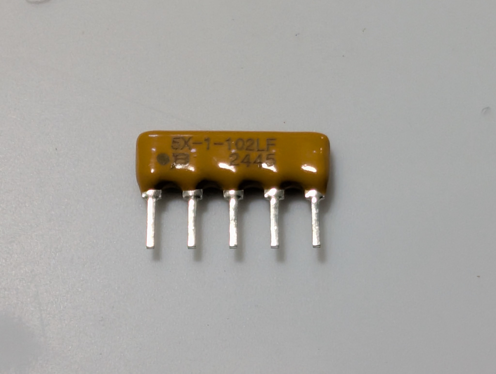
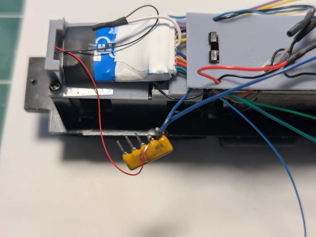
Instead of soldering a resistor for each LED and trying to heat shrink and cram them all in, I use a resistor bus network—sometimes called a bussed resistor array. These little guys come in handy when space is tight and you’ve got multiple LEDs to hook up.
The one I’m using is a 5-pin package:
- 1 common pin (where the blue wire goes)
- 4 outputs, each with its own built-in resistor
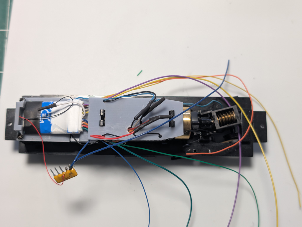
So it’s like having four separate resistors neatly packed into one tiny component. I mount one up front to handle the headlight and front ditch lights, and another in the back for the rear light, rear ditch lights, and beacon. Keeps the wiring clean, compact, and easy to trace later if I ever need to troubleshoot.
Once everything is wired in, I will shrink-wrapped the bundle. But I am not there yet.
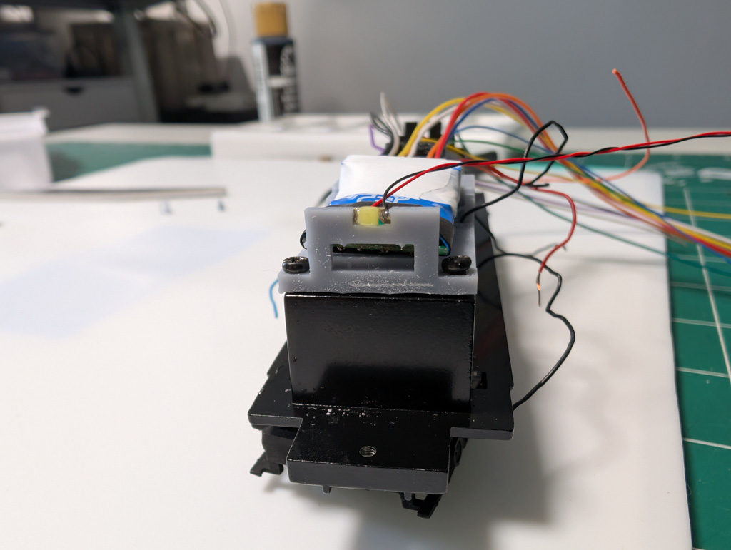
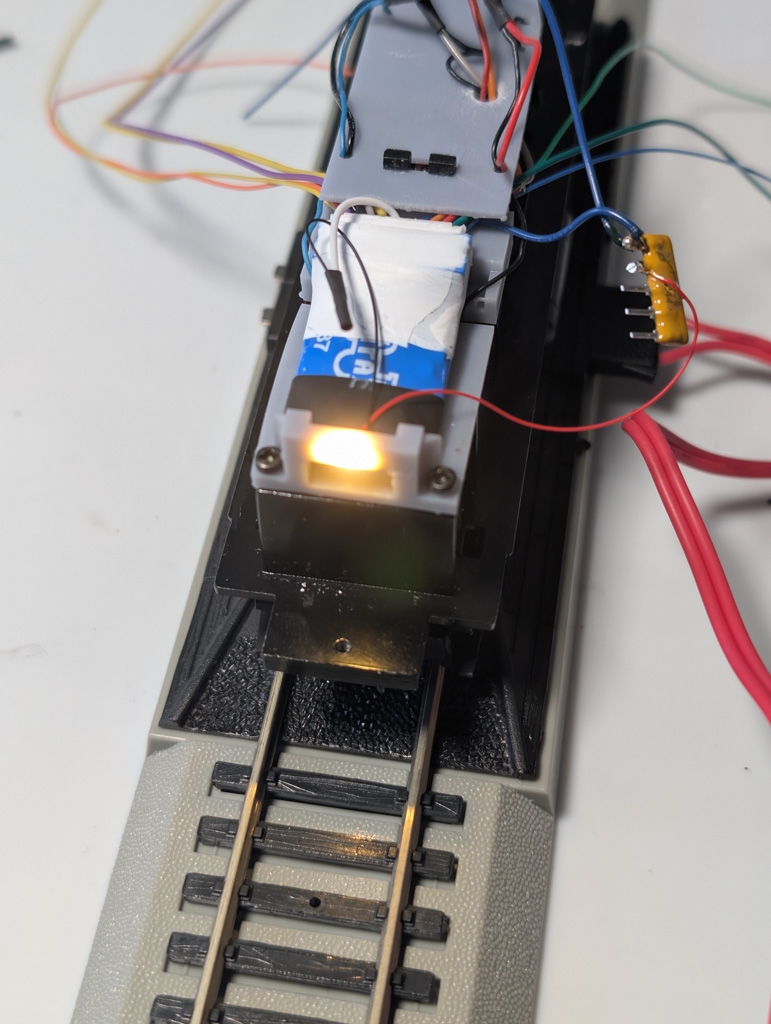
And The Test Run
Ok, Drumroll – lets give it a test to make sure that things work up to this point…. And yep—it lives! The smoke stayed inside. And that is a good thing.
What’s Next For The KNR90?
The rest of the lighting will be wired after I finish painting the shell.
Next step? Paint. Stay tuned for that one.
Articles in This Series
- Restoring & Upgrading a Proto 2000 SW900 – The KNR 90 Rebuild : Overview
- Restoring & Upgrading a Proto 2000 SW900 – The KNR 90 Rebuild : History
- Restoring & Upgrading a Proto 2000 SW900 – The KNR 90 Rebuild : Tear Down
- Restoring & Upgrading a Proto 2000 SW900 – The KNR 90 Rebuild : Paint Removal
- Restoring & Upgrading a Proto 2000 SW900 – The KNR 90 Rebuild : AAR Type A Trucks Replacement
- Restoring & Upgrading a Proto 2000 SW900 – The KNR 90 Rebuild : DCC Decoder Install
- Restoring and Upgrading a Proto 2000 SW900 – The KNR 90 Rebuild – Painting
- Restoring & Upgrading a Proto 2000 SW900 — The KNR 90 Rebuild: Final Wiring and Ditch Lights