
Inspiration and Prototype Research
Removing the Factory Logic Board from Your Pro 2000 SW1200
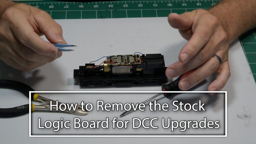
Table of Contents
Watch Along: Factory Logic Board Removal
Logic Board Removal for DCC Installation
As part of the Florida East Coast switcher upgrade, we’re removing the factory-installed logic board from the Pro 2000 SW1200. That small board only controls the directional lights, so stripping it out and separating the pickups and motor is a required step before you drop in a DCC decoder.
Tools You Need
All you need is a pair of tweezers to move the wires around, a flat-blade screwdriver to press the tabs, and wire cutters. Some people prefer to desolder the leads, but cutting them flush with the circuit board is faster and gives you more lead room.
Cutting the Wires
Start by loosening each wire at the board—on mine they’re red and blue, but colors vary. Move the wires to free them up, then use your cutters to snip each lead as close to the board as possible. Repeat on both sides until most of the wires are cut, then push the loose ends out of your way.
Removing the Logic Board
With the wires cut, flip the board over and press the tabs on the back with your screwdriver. Once they’re loose, the board will pop forward. Then press the tabs at the front the same way to fully release the board and pull it free.
Tracing and Organizing Wires
After the board’s out, pull the remaining wires from the bottom. You’ll find the pickup leads are color-matched—red on one side equals red on the other, same for blue—and the motor wires are easy to identify (red and black). Straighten them out so they’re ready for decoder hookup.
Ready for the DCC Decoder
Now that the logic board is gone and your wires are organized, you’re all set to drop in the DCC decoder. I’ll cover that next—stay tuned!
If you run into any snags or have questions, leave a comment below. I’d love to hear how your logic board removal went and help troubleshoot.